




>
Flow Meter

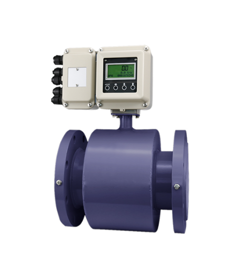
Slurry Electromagnetic Flowmeter

Slurry Electromagnetic Flowmeter

Application Scenario

The electromagnetic flowmeter consists of two main parts: a flow sensor and a transmitter. The sensor measurement pipe is equipped with excitation coils above and below. After passing the excitation current, a magnetic field is generated and passes through the measurement tube. A pair of electrodes are installed on the inner wall of the measurement tube and come into contact with the liquid, leading out the induced electromotive force and sending it to the transmitter. Assuming that the magnetic field intensity (B) generated by the electromagnetic induction coil is constant, the induced voltage (Ue) generated is proportional to the fluid velocity (v), the constant (C), and the cross-sectional area of the pipeline and pipeline (A) are known, the volumetric flow rate (Q) can be calculated using the following formula: Ue=C*B*L*v Q=v*A The flow rate is linearly related to the fluid velocity, with a simple principle and accurate measurement.

Advantage

High measurement accuracy.
Wide measurement range.
Long service life.

Specifications

Parameter Type
Specific Value
Structural Form
Integral type (with top-mounted display) / Split type (sensor + remote display)
Nominal Diameter (DN)
DN10 – DN2000 mm
Nominal Pressure
0.6 – 4.0 MPa
Accuracy
0.5% / 0.3% / 0.2% (selectable by model)
Lining Material
PTFE / PFA / FEP / Neoprene / Polyurethane (by medium)
Electrode Material
316L / Hastelloy C-276 / Titanium / Tantalum / Platinum
Protection Rating
IP65 / IP67 / IP68 (selectable)
Conductivity
>=5 uS/cm
Flange Standard
GB / DIN / ANSI / JIS (optional)
Power Supply
220V AC / 24V DC / 3.6V (battery)
Output Signal
4…20mA
Communication
RS485 / HART

Access detailed technical specifications by down loading our datasheet.

Download

Get all the technical details you need by downloading our product specs.